Work Instrumentation & embedded updated August 2016

Bicom Electrode switch

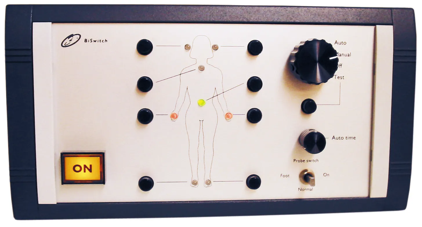
Add-on switch that routes a Bicom instrument’s output between electrode positions — by hand, or stepping automatically on a timer — with the positions laid out on a body diagram across the front panel.
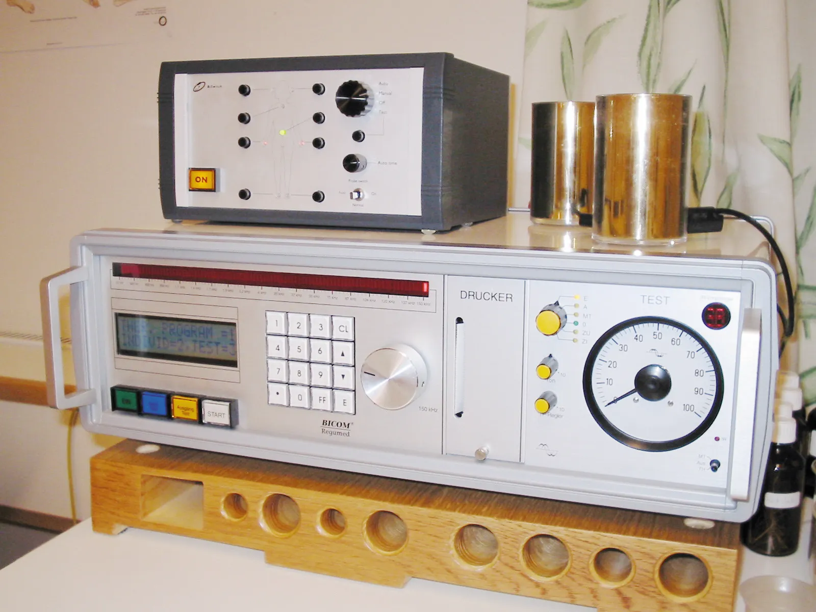
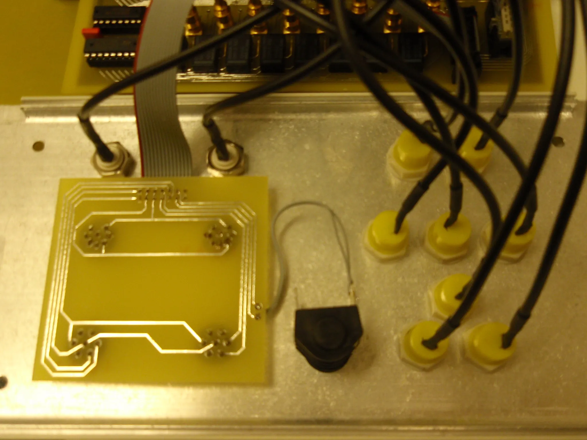
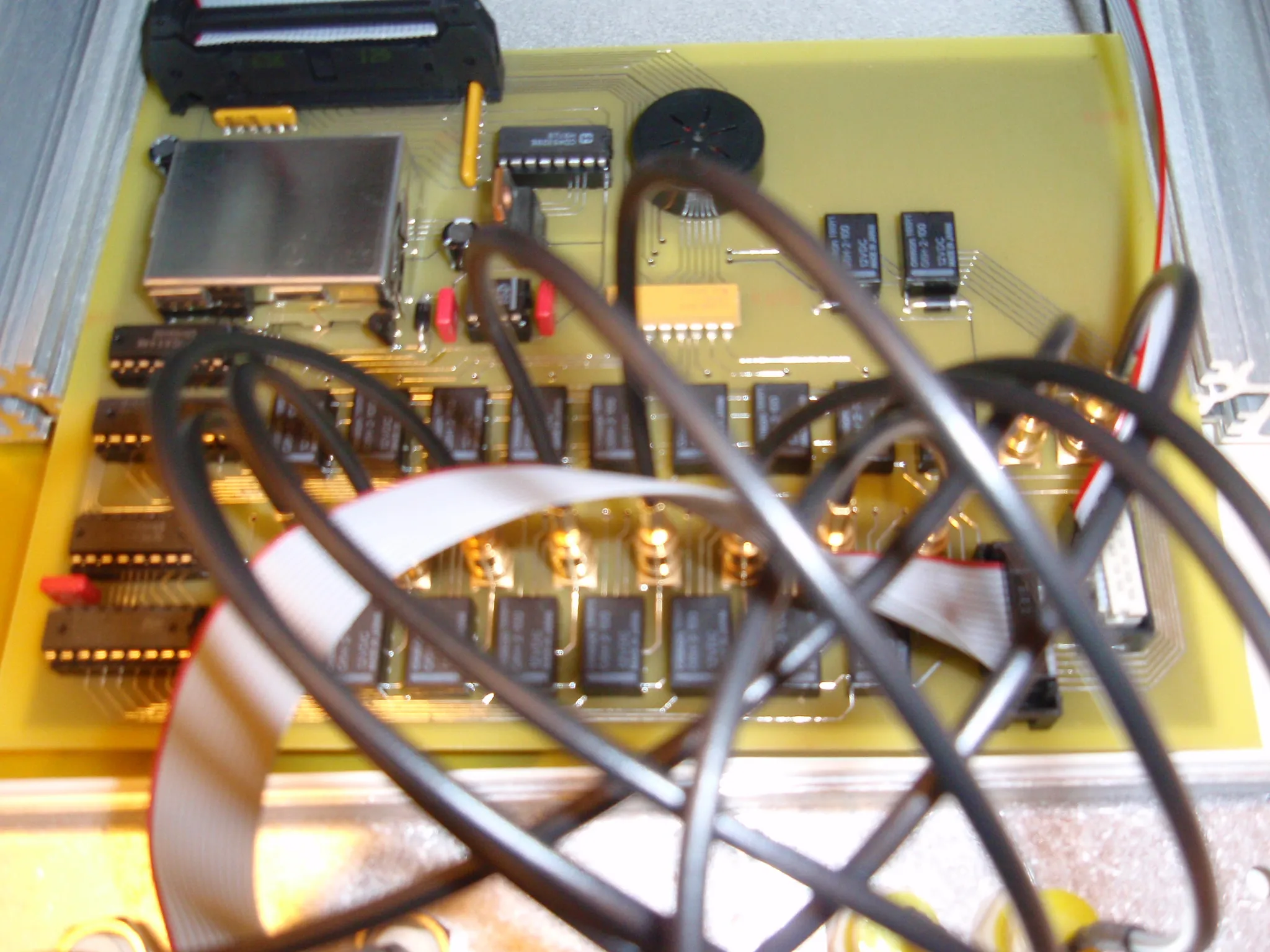
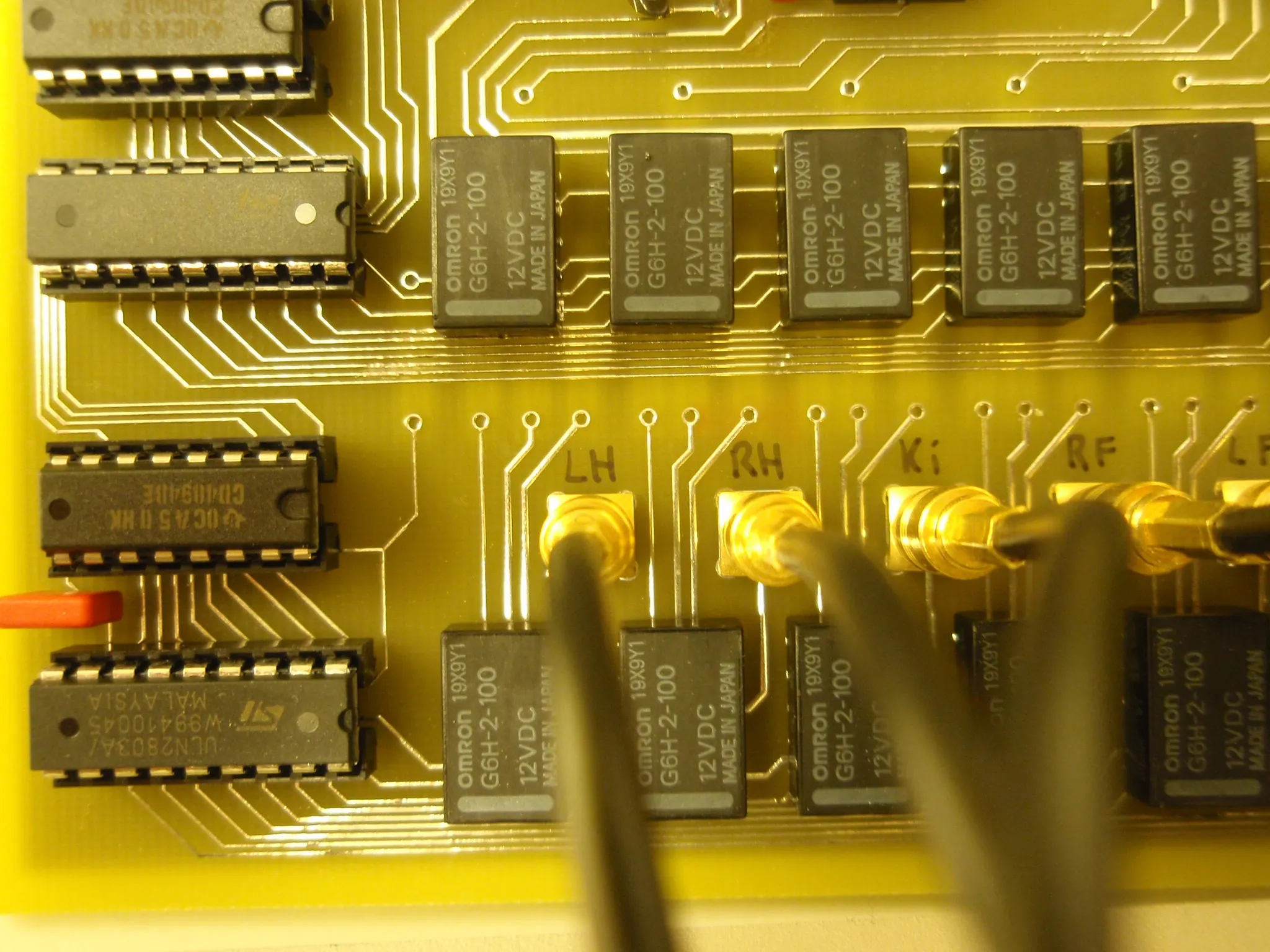
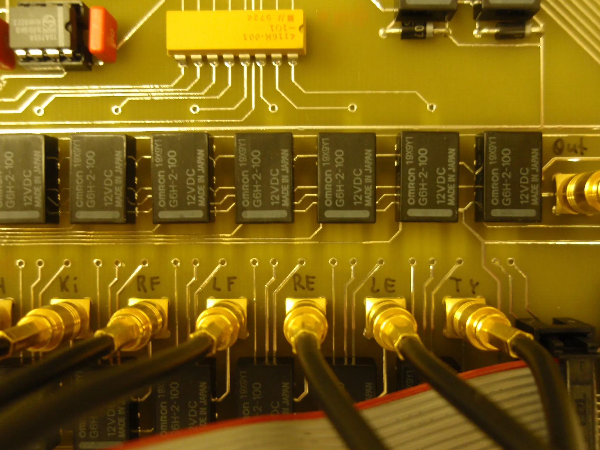
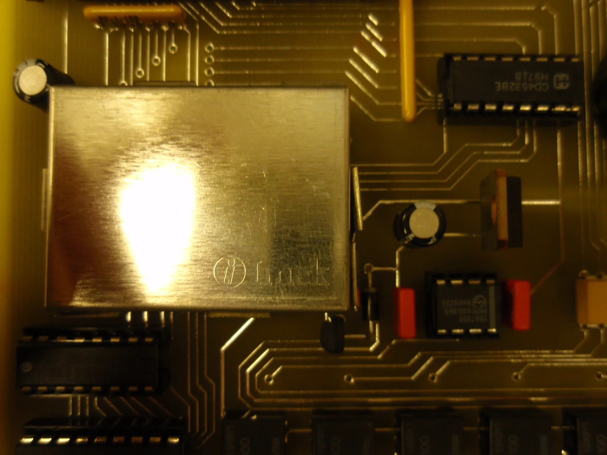
FramBicoBisw Inside the switch: a hand-etched board with wide traces, a bank of relays and gold-plated jack sockets above it on a ribbon cable, and the yellow panel sockets with their leads The main board from above: logic in sockets, a shielded module, a piezo buzzer, and a bank of Omron 12 V relays feeding the gold-plated jack sockets Close-up of the relay bank: Omron 12 V relays and CD4051 multiplexers driving jack sockets hand-labelled LH, RH, Ki, RF and LF Further along the same row to the socket marked Out, with the electrode sockets beneath labelled Ki, RF, LF, RE, LE and TY Close-up of the shielded module, with a CD4528 monostable and a TDA7050 audio amplifier beside it Fram

instrumentationhealthcareembedded

← Work